
The start of the article is not about spanning tree protocol but regarding spanning tree.
Why do we even should consider and perceive a spanning tree? Because the name of the protocol itself suggested us to check out.
Then, what is this spanning tree?
A spanning tree is an undirected graph in which all the vertices get connected. That means,if A,B,C are connected then the possibilities of spanning tree formed as follow,

This shows in what manner the possibilities of the graph can be formed from above diagram.
The separate set of circuit equations are generated by applying spanning trees in the electrical networks.
What is Spanning Tree Protocol?
Now, what is the spanning tree protocol?
Spanning Tree Protcol (STP) is a protocol that is used to avert the loop forming when we use redundant switches. STP runs on switches and bridges by forming loop-free. This STP is the layer 2 protocol. The original standard protocol of STP is IEEE 802.1D.
The main goal of STP is to discard the loops and to obtain this, three steps are followed.
a)The selection of one switch as the root bridge that is the central point in the network.
b)It picks up the shortest path which is of low cost from a switch to the root bridge.
- c) Blockage of the links are observes and closes and conserving these links as backups.
STP can retrieve the blocked link to active if one of the links gets a break so it can conceal the fault tolerance for a network.
Example of Spanning Tree Protcol (STP)
Consider the three switches which are interconnected with each other. If there is no STP presence then looping problems may occur with several other problems.

Let us take a peek at some loop concepts and the problems, the switch will forward the frame to every port except the one that receives it, this is the reaction of the switch for broadcast or unicast message with the unfamiliar address.
So the switch B sends the broadcast message to both switches A and C and these switches will forward hat message out of all other ports. Switch A and C receive those broadcast messages and again they forward it out of all up to their ports. Then the loop is created.
Similarly, switch C starts to send a broadcast message then switch A sends another broadcast message.
These broadcast messages are sent all the time so, more frames are built onto the loop. We can assume the network blockages from this, are called broadcast storms, and these broadcasting messages will become extensive until the switch is damaged or when the switch is delinked and reloaded.
Consider switch B again for transmitting the broadcast messages and the other switch like A will receive and learns the MAC address of that message at the same time if the switch C also sends the message with the same MAC address then these messages are stored in different ports and get updated in MAC address table.
So, this is the second drawback that is the unstable MAC address table.
Another drawback appears when host B wants to send the data to host A, first it goes to the switch of host B. As switch B doesn’t know the location of the host A MAC address it will send the frame out to all other ports.
Then switch C receives the data which sends it to host A and again switch A also received the same data so even it sends it to switch C so the duplicate frames are formed and sent.
The solution to these troubles is, the switch simply blocks one of the ports but the switch still receives the data but it just ignores it so the above-mentioned drawbacks get covered.
Here we need to observe the procedure of STP and the strict rules it impose to block the port.
Step by step process,
a)Electing a root bridge
b)Present the root interface in a forward state
c)The non-root switches selects their root port
d)The links that remain selects a designated port.
e)The switch will see only the transmitting one and block all other ports.
A working example of STP by imposing the rules
In a local area network just visualize as having four switches A, B, C, D that are connected. Between these interconnected switches, there are few redundant links.

For an instance, from switch C to switch A there are two paths CA and CDBA.
In the network availability, link redundancy is mandatory. Because of the redundancy link layer, 2 loops are created. The network can block the unwanted links that cause loops by utilizing STP.
Firstly selecting the root bridge based upon the lowest bridge ID and the priority is taken from MAC address.
Consider switching A as the root bridge with MAC address 0000.0000.1111. and the other switches will be choosing the path that is the least path to reach the root bridge.
The cost of the path is based on the bandwidth it has, the higher the bandwidth the lower the path cost.

Include the diagram above for the better understanding.
Observe that switch B that has two paths to reach the root bridge, one is BA and the other is BDCA.
while BA has the least cost of 2 and BDCA has 2+4+1=7.
So, the BA link is chosen as the path to reach the root bridge A then the switch B port is taken as the root port that is a least-cost path to the root, and the other side of switch A that is linked is taken as a designated port.
Similarly from switch C to the root bridge, there are two paths as CA with 1 and CDBA as 4+2+2=8.
At switch C the root port is selected and at the root designated root is chosen.
For switch D there are two paths as DBA with 2+2=4 and DCA with 4+1=5. So it chooses the path DBA to reach the root and at the switch D root port is selected along with another side of switch B designated port is picked.
The non-root switch may have several designated ports but not many root ports. The root port should only be one.
From the above description, all the switches are selected for their finest path.
And also to avoid the loop the link of DC needs to be removed so for this, at switch D, one port will be a blocked port, and the other at switch C as a designated port.
The blocked side port might receive the frames but it doesn’t forward the frames instead it merely drops them.
The selection of the root bridge is the main course of action to determine all the steps.
BPDU that holds the information about STP is called the bridge protocol data unit. This BPDU is utilized by the bridges and the switches to share information among themselves and also for determining the root bridge the BPDU is used. And for link blockage and port roles and states are also decided by it.
Its main purpose is to compose the loop-free network. In the frame relay of BPDU, there are 11 frames the 3 most essential frames are root ID, root path cost, and bridge ID.
Root bridge BID is also meant to be the root ID and BID is a bridge ID of the sender’s BID. The best path to reach the root bridge is the root path cost
At first, when three switches are connected A, B, C all the switches are considered themselves as superior and root so switch A sends its BPDU frame to each other switches. Similarly, the other switches are also sent their BPDU and all will be having the root path cost as 0 but there should be only one root.
So, when switch A sends the BPDU the other switches check their bridge ID that haves lower than both B’s and C’s, and they get discarded. And their root IDs are replaced with A’s bridge ID also their root path cost is updated.
Types of Spanning Tree Protcol (STP)
a)The original STP, standard STP, or 802.1D and it is the common type of STP.
b)PVST+, this is the improvement of Cisco by adding a per VLAN feature that is per VLAN spanning tree.
c)RSTP, haves faster convergence that is an upgraded version of STP.
d)Rapid PVST+ is also a development of Cisco for RSTP by adding the per VLAN feature.
Features of Spanning Tree Protcol (STP)
a)BPDU, this is used by STP for permitting the communication among the switches based on the information such as root bridge, timers, and root cost.
b)Root bridge, that maintains the lowest bridge ID in a switch topology.
c)Root path cost, the cost of the path to traverse through the ports from a non-root to the root bridge.
d)Bridge ID, it consists of MAC address and the bridge priority. This is commonly referred to as the recognization of a switch.
e)The 4 port roles of STP,
- Root port, which is placed on non-root bridges that haves switch ports along with best cost path to reach the root bridge.
- Non designated port, the port of the switch that is blocked and doesn’t designate for transferring.
- The designated port is the one that exists on root and also on non-root bridges too. This is used to forward BPDU on a LAN segment.
- Disable port, the port that is closed.
STP has a very helpful feature for network convergence to accelerate the speed and also to protect the spanning tree by EtherChannel, port fast, and cisco BPDU guard.
Advantages of Spanning Tree Protcol (STP)
Simple and understandable to make this use.
- STP is already an examined technology.
- Gives backbone support for switches and the bridges.
- Supply of redundancy links and avoiding unwanted loops.
- If the foremost connection is stopping then the various backups are proposed to become active.
Disadvantages of Spanning Tree Protcol (STP)
- It consumes some time for traversing.
- The loss will occur and leads to the formation of loops when the common type of mistakes or errors happen in STP.
Configuration of Spanning Tree Protcol (STP)
To see the configuration of STP and the way it works we use packet tracer like cisco. In this let us consider the switch structure, where switches are present such as switch A, B, C, D.
If we want to configure one of the switches firstly we need to log in to that switch.
Let us assume we are logging into switch A by clicking it and go to CLI.
Under that particular switch command like switch A, type “show spanning-tree” by this command the spanning tree of VLAN will be displayed along with that specific root ID, bridge ID, and its interfaces. These consist of the priority of the switch, MAC address of the switch, and also if the switch is considered as root bridge or the non-root.
It also shows the interfaces to which the specific switch is connected to another and its role, state, and cost towards them along with priority.
To see the specific designated port role, type “show spanning-tree interface FastEthernetA/B” which means interface from A to B then it displays the values that are associated or given.
To make one of the switches the root switch again we need to go to the CLI of the command-line configuration. For this, at first, we need to know the range at which we need to give the priority value. so type “spanning-tree VLAN 1 priority ?” the “?” This Demonstrate the range in which the priority should be taken along with the emphasis on the increased significance priority of the bridge.
“spanning-tree VLAN priority 3045” exhibits the shortest priority value than different switches and then this is deemed as the root switch. This is a command.
To specify the range type “spanning-tree VLAN 1-4000”.
To disable the whole VLAN of STP type “no spanning-tree VLAN 102”
To disable STP on a port basis type,
- a) interface g1/2
b)no spanning-tree VLAN 102.
Difference between STP and RSTP
Difference between spanning tree protocol and rapid spanning tree protocol are following.
-
Rapid Spanning Tree Protocol
It is recognized as a rapid spanning tree protocol.
This is RSTP IEEE 802.1W.
It infers three circumstances as discard, learn, forward. These are the STP ports that are the same and don’t traverse an ethernet frame or study the MAC address.
Hence, RSTP places all in the state called discarded then the study and ports that are forwarding will continue to stand less or more.
Maintains two more ports besides that are backup port and alternate port.
The timers are only used for backward compatibility.
Have a fast transition.
Considers 0 to 7 bits for use.
-
Spanning Tree Protocol
This is an STP IEEE 802.1D.
This comprises two ports called the root port and designated port.
And the port states of STP were disabling, listening, forwarding, blocking, and learning.
For convergence timers are hello with 2sec, max-age with 20sec, forward delay timer with 15sec.
Have a slow transition.
Usage of two bits that are bit 0 and bit 7.
Summary:
Spanning tree protocol that runs on layer 2 protocol that is a data link layer that gives the finest structure for traversing among the devices like switch and routers without forming any kind of loops. It observes all the links that are formed in the network. This can be made possible in a way of redundancy and the shortest way to travel to reach the root switch.
Spanning Tree Protocol in More Details
You must be thinking what is spanning tree protocol and why we need it? The Spanning tree protocol is a layer 2 protocol i.e. data link layer of the OSI model. This protocol helps to avoid switching loops in the network that may lead to more bandwidth utilization, mac database instability, and broadcast storms.
Whenever there are two or more than two links between the switches for the redundancy purpose then STP comes into the picture.
It uses a spanning tree algorithm and by using it blocks the redundant links and according to the STP election process, some ports will remain active. The STP is enabled by default on all the cisco switches. There are different types of STP available:
1D: This is known as the common spanning tree protocol and it is enabled by default in all the switches. It is a standard developed by IEEE wherein the single root bridge is elected for the whole topology and other switches become a non-root bridge. It takes 30 seconds to complete the whole process of the STP election.
PVST+: This is the Per Vlan Spanning tree+ and it is cisco proprietary and by default enabled for the Cisco switches. It helps to elect the root bridge per VLAN basis. It is helpful in load balancing as we have separate root bridge for each VLAN.
1w: This is the rapid spanning tree protocol and it is an IEEE standard that works faster than a common spanning tree and comes with the less STP port states. The election process is the same here also that is one root bridge for the whole topology.
Rapid Per VLAN spanning tree+: This is the Cisco proprietary protocol and works faster than PVST and the process is the same as PVST that is the root bridge for each VLAN. It requires more CPU resources than normal STP.
1s: This is the multiple spanning tree protocols and it helps to choose the single root bridge for the group of VLANs. Hence, it provides more load balancing and faster than other versions of STPs.
How STP Root Bridge Election Process works
Let’s understand this by using the following diagram:
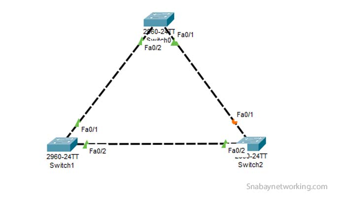
In the diagram we have three switches 0,1,2 and you can see the port Fa0/1 of switch2 is in blocking state. After the STP election process, that port moved into the blocking state, and if the link between switch 0 and 1 or switch 0 and 2 goes down then the port f0/2 will go into the forwarding state.
Want to know which switch becomes the root bridge?

As you can see Switch1 becomes the root bridge and all the ports of the root bridge always remain in the Designated role and state be forwarding. There are several factors through which STP chooses Switch1 as a root bridge. Following are the factors when it comes to choosing the root bridge:
- When all the three switches come online then BPDU(Bridge Protocol Data Unit) messages are shared among the three switches. BPDU includes the Bridge id and Bridge id is a combination of Bridge Priority and mac address and it is of 8 bytes total.
- The switch with the lowest Bridge Id becomes the Root Bridge. By default, the bridge priority of all the cisco switch is 32768 and if the bridge priority is the same for all the cisco switch then the mac address will be tie-breaker, the switch with low mac address will become the root bridge.
Bridge ID= Bridge Priority(2 Bytes) + Mac Address(6 Bytes)
- All the ports of Root bridge will always be in forwarding state and role always be designated.
- We may change the priority of the cisco switch if we want to make the particular switch as a root bridge.
Note: Root ID is the Root Bridge information and Bridge Id is the Information of local switch(Non-root Bridge)

The Switch0 is the non-root bridge and one port of every non-root bridge must be Root port and always in forwarding state. Now, you must be thinking about how switch0 elects the Fa0/2 as a Root port. To select the Root port see the following points:
- There are some STP costs available according to the link type:
10 Gbps-2, 1Gbps-4, 100Mbps-19, 10Mbs-100.
In our topology, we are using fast Ethernet of 100Mbps so the cost would be 19. Now, the switch0 will look for the path to reach the root bridge that is Switch1 with minimum cost. The path from f0/1 of switch0 would cost the total 38 but the path from f0/2 would cost the total 19 so that’s why switch elect f0/2 as the root port.
- After selecting the root port, now we need to select the Designated and non-Designated port. Again, we check the least cost to reach the root bridge but in our topology to reach the root bridge the cost is the same for both the ports( f0/1 in switch0 and f0/1 in switch2) i.e.19. Now we need to check the Bridge id of the sender switches i.e switch0 and switch2.
- As we can see in the above screenshots, the mac address of switch0 is lowest than the mac address of switch2. Now, in that case, the port f0/1 of switch0 will become the designated port and be in forwarding state. However, the port f0/1 of switch2 will become the non-designated port and moved to a blocking state. When the link between switch0 and switch1 goes down then the link between switch0 and switch2 will get started and f0/1 of switch2 will be moved to the forwarding state.

Difference between Root Port and Designated Port
- Every switch has only one root port and may have multiple designated ports.
- The root port is directly connected to the root bridge while the designated port is the port not directly connected to the root bridge but still forwarding traffic from the other network segment.
- Root ports listen to all the BPDUs coming from the root bridge while designated ports transmit BPDUs ahead.
STP Port States
There are five STP port states:
- Disabled
- Blocking
- Listening
- Learning
- Forwarding
A disabled port is a shutdown port that means it is administratively down. In this state, the port is not allowed to do anything and we can say, STP does not run in this state.
Once that port is administratively enabled, the port will be moved to the blocking state(BLK). The port still cannot do much, no frame forwarding, no frame receiving, and therefore no dynamic learning of MAC address. In this state a port is allowed to accept BPDUs from the neighboring switches.
Listening is the next state. In this state the port is listening for BPDUs and a port is allowed to send BPDUs and can accept BPDUs, permits port to take part in the root bridge election. A port in listening mode cannot forward or receive frames and thus the port cannot learn the mac address.
Learning is the next state. A learning port is not forwarding frames but it is learning mac addresses and adding them to the switch mac address table. A port in the learning state continues to do the process of sending and receiving BPDUs.
Forwarding is the next state. A forwarding state allows a port to forward and receive frames, send and receive BPDUs and continue to learn mac address. This is the only state where the port is forwarding frames.
How BPDU generated and How BPDU works
There are three switches in our topology mentioned above and when all these switches come online then they start to share BPDU messages and after every two seconds BPDU messages are shared among the switches to select the root bridge. These BPDU messages include the Bridge Id information of every switch and helps to decide who should be the root bridge. After the selection of the root bridge, the root bridge will be allowed to generate BPDUs. All the non-root bridges will not be allowed to generate BPDUs, they can only receive and forward the BPDUs.
The Root bridge election process never ends if the new switch comes with the lowest Bridge Id then it would become the Root Bridge. Every switch in the topology sends out BPDU messages after every 2 seconds which includes the bridge id, port cost, root path cost, and many others. The non-root bridge switches in the toplogy may generate only TCN BPDUs( Topology change notification). Whenever there is a change in the topology then non-root bridges may start to generate the TCN BPDUs to inform the root bridge that is something added or removed from the topology.
Important Spanning Tree Protocol Timers and their default values
The available STP timers are Hello timer, Max age timer, and forward delay timer.
The Hello timer is by default 2 seconds. Every switch sends out BPDU messages after every 2 seconds with the values like root cost, path cost, bridge id. We may change the default hello timer and set it accordingly and to deploy the Stp timer deployment in the whole topology, you need to change it in the root bridge.
Command to change default Hello timer:
Switch1(config)#spanning-tree vlan 1 hello-time 6
In the above command, we change the hello timer to 6 seconds.
The Max-Age time timer is by default 20 seconds and it indicated for how long a switch will keep the BPDU message before discarding it.
Switch1(config)#spanning-tree vlan 1 max-age 24 In the above command we change the max-age timer to 24 seconds.The forward delay timer is by default 15 seconds. A forward delay timer is the length of the listening and learning STP states with a default of 15 seconds for every individual state.
Switch1(config)#spanning-tree vlan 1 forward-time 18
In the above command, we change the forward-timer to 18 seconds.
Topology changes in the Spanning Tree Protocol
 As mentioned above in the article already that whenever there is a change in the network topology then the non-root bridges generate Topology change notification BPDUs and Topology change Acknowledgement BPDUs until it reaches the root bridge. Once the root bridge receives the Topology change notification then the root bridge generates the Configuration BPDUs with TCN bit set and it will be forwarded to every non-root bridge in the whole topology so that all may get aware of the topology change.
Spanning Tree Protocol Convergence
The STP convergence takes place when port goes to either blocking or forwarding state. When the switches first come online then it takes 30 seconds to select the root bridge and decides which port needs to be blocked. In the above topology, Fa0/2 port of switch3 is in a blocking state. If the port f0/1 goes down then Fa0/2 will move into the forwarding state and it will take 30 seconds to come into the forwarding state. If the port connected to switch is in blocking state and another port is in forwarding state then when the forwarding state port goes down then other blocking state port will take only 30 seconds to come up like in switch3.
 If the port between switch0 and switch1 goes down then it will take a total 50 seconds for the port fa0/2 to come up. This is because the link between switch0 and switch1 is not directly connected to the fa0/2 port of switch3. When the port goes down then the max-age timer starts and it will wait for 20 seconds to receive BPDUs and when BPDUs are not received then port fa0/2 goes into listening and learning state which takes 30 seconds and the total is 50 seconds.
Where to place the Spanning Tree Protocol Root Switch(Root Bridge)
During the STP root bridge selection process, the switch with the lowest priority id becomes the root bridge and if the priority value is the same for all switches then the mac address comes into the picture. The switch with the lowest mac address becomes the root bridge. The default priority of the cisco switch is 32768.
Here, priority is 32769 because the switch comes under vlan 1 so plus 1 is added for the VLAN.
You need to take care of some things while placing the root bridge if you are thinking that the STP selection process will select root bridge automatically then it may lead to many problems as if your network topology has old switches and generally old switches have lowest mac address and thus as per the STP election process that old switch may become the root bridge.
As we know old switches have less CPU and hardware resources so they would not be able to handle the large network traffics and thus it may lead to packet loss, slow speed, and many more.
To avoid this, you need to make a high-end configuration switch as root bridge manually and the root bridge should be placed in the central area of the network so that it may provide the best path to all the other devices. Generally, the root bridge switch available in the distribution layer as the switches working in the distribution layer have high configuration and can optimize network traffics.
What is Spanning Tree Protocol Uplink Fast?
As we can see in the above screenshot, port fa0/1 of switch2 is blocked and if you go with normal STP and thus if the link fails between switch1 and switch2 then it will be approximately 50 minutes before the blocked port may come up and that is bad for the network topology.
With the help of Uplink fast feature, the port fa0/1 can be used to forward the frames without any delay i.e. immediately. The concept of the uplink group is used which includes the root port and the other blocked port like in the case of switch2.
When the port fa0/1 goes down then the port fa0/1 comes up immediately without going to listening and learning state. If there are multiple blocked ports available then the port with the lowest cost to reach the root bridge will be chosen.
We cannot enable uplink feature per-port or per-VLAN basis. It is enabled globally in the cisco switch. When the switch detects that the original root port comes up and thus the original root port would become the available path and port which comes up from the blocked state would go again into a blocked state.
When we apply the uplink feature on the switch, it does perform two immediate actions. First is, it increases the priority of switch to 49152, and second is, it increases the port cost by 3000. When the link between switch1 and switch2 goes down and thus there will be invalid entries available to send frames to PC0 and in that case, switch2 sends and floods dummy frames to switch0 and those dummy frames include every single mac address entry in switch2.
The flooding updates the mac address of switch0 and then frames are forwarded correctly.
Command to enable Uplink fast:
Switch2(config)#spanning-tree uplinkfast
What is Spanning Tree Protocol Backbone Fast
 The Backbone feature is a cisco proprietary and it helps the network to recover from the indirect link failures as soon as possible and the specific word here is Indirect. In the above screenshot, if the link between switch1 and switch4 goes down then it would take up to 50 seconds to come to forwarding state for fa0/1 port in switch0. In our case, switch1 is the root bridge, when the link goes down then switch4 assumes itself as the root bridge and thus switch0 receives BPDUs
from the switch1 and switch4 as the BPDUs from the root bridge. Now, switch0 does compare the priority in each BPDUs received from the switch1 and switch4 and will notice that switch4 has lower Bridge ID and thus makes switch 4 BPDUs inferior and at last ignores the BPDUs receives from Switch4. Once the max-age timer of switch0 comes to zero then the port leading to switch4 will be moved into the listening state and thus start to relay the information coming from the switch1(higher BPDU).
Backbone does not help to move the port immediately to forwarding but it does reduce the convergence time from 50 seconds to 30 seconds by eliminating the Max-Age timer.
Command to enable backbone fast
Switch1(config)#spanning-tree backbonefast
What is Spanning Tree Protocol Portfast
This Portfast feature is helpful when we want to move port from blocking mode to forwarding mode. It avoids the listening and learning state of the port. We usually enable Portfast for the end hosts that are connected to the switches and ports are known as access ports connected to end hosts. In which scenario we enable Portfast in the end hosts? If the end hosts are having some problems to get the IP address from the DHCP server and thus we enable Portfast to avoid listening and learning state. You cannot enable Portfast for the trunk ports.
Command to enable Portfast
Switch2(config)# spanning-tree portfast
We may enable it per-port basis also.
How to configure and verify Spanning Tree Protocol Portfast
When the pc first connects with the switch then it goes to perform the listening and learning state to make the port in forwarding mode. You can see in the screenshot, first, it goes to the listening state for the 15 seconds, and afterward learning state for the 15 seconds that is total would be 30 seconds.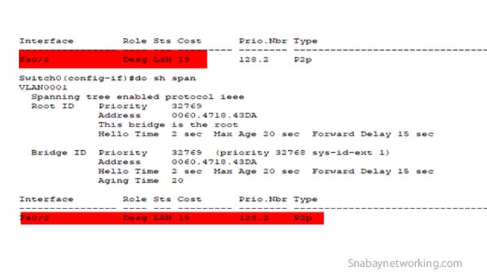
If we enable the Portfast feature then the port fa0/2 will be moved into the forwarding state without any delay.
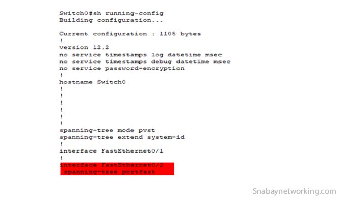 To verify you may use show running-config command. In the above screenshot, you can see int fa0/2 is configured with the Portfast feature.
How to enable and disable spanning tree protocol
We may enable or disable the Spanning tree protocol. However, the STP is by default ON in all the Cisco switches. It is recommended to disable the Spanning tree protocol as it creates switching loops and may lead to mac database instability and broadcast storms.
Following are the commands to enable and disable the spanning tree protocol :
For enabling
Switch0>
Switch0>enable
Switch0#configure terminal
Enter configuration commands, one per line. End with CNTL/Z.
Switch0(config)#span
Switch0(config)#spanning-tree vlan ?
WORD vlan range, example: 1,3-5,7,9-11
Switch0(config)#spanning-tree vlan 1
Switch0(config)#
Switch0(config)#exit
Switch0#
For disabling
Switch0>
Switch0>enable
Switch0#configure ter
Switch0#configure terminal
Enter configuration commands, one per line. End with CNTL/Z.
Switch0(config)#
Switch0(config)#no sp
Switch0(config)#no spanning-tree vlan ?
WORD vlan range, example: 1,3-5,7,9-11
Switch0(config)#no spanning-tree vlan 1
Switch0(config)#do sh spanning-tree
No spanning tree instance exists.
Switch0(config)#
After disabling you may verify it by using the command Show spanning-tree.
[…] network load balancer works on 4 layers of open Systems Interconnection (OSI) layers. Millions of queries can be handled […]